The Next Leap
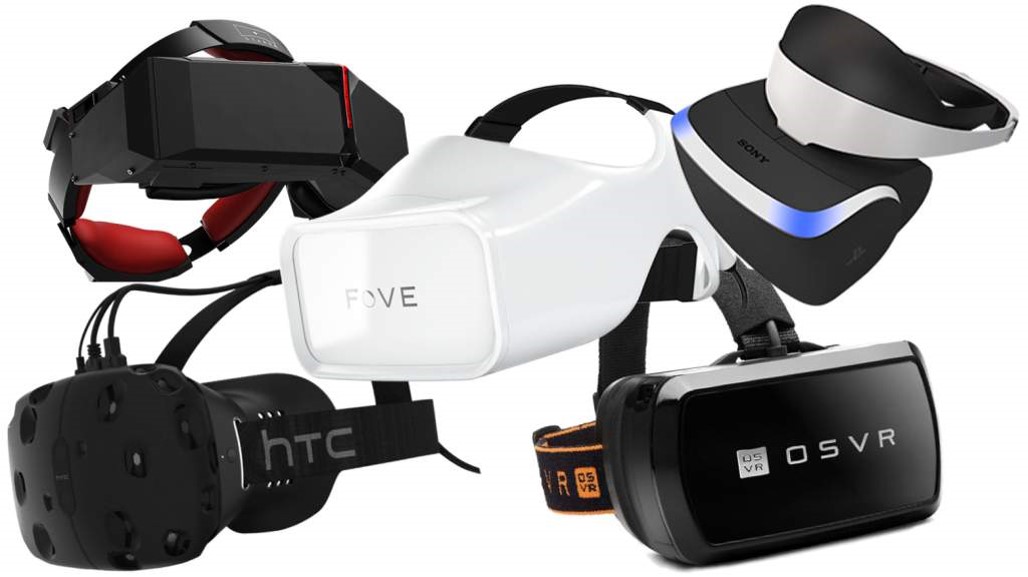
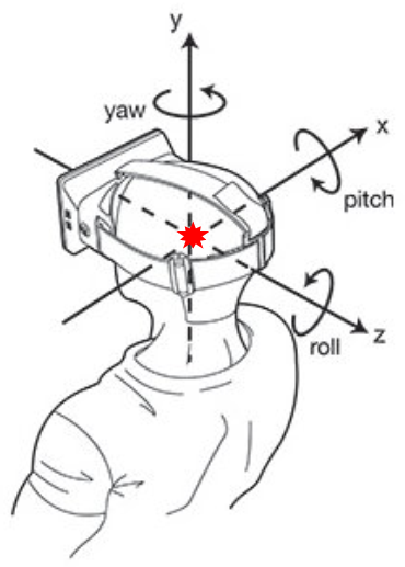
Virtual reality is poised to change how the world consumes entertainment, communicates, and explores new worlds. Many companies are working to bring a seamless virtual reality experience to the market. For head-mounted display systems, this requires accurately tracking the motion of the user's head. As the user looks about in the real world, the display of the virtual world must closely reflect their motion.
We developed a virtual reality headtracker based on an Extended Kalman Filter (EKF) with representative measurement models. We evaluated our system for various sensor placements, then incorporated a novel accelerometer constellation design. Our results demonstrate the accelerometer constellation improves head-tracking performance over traditional systems, at the cost of additional computational complexity.
Building a Headtracker
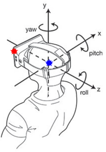
There are several approaches to constructing a headtracking sytem. LaValle et al. outline the process by which the Oculus Rift headset tracks user head orientation and position. The headset incorporates measurements from a 3-axis gyroscope, accelerometer, and magnetometer. We describe this approach below:
- Update approximate head orientation with gyroscope measurement
- Compute expected gravity and magnetic field vectors at estimated orientation
- Fuse accelerometer and magnetometer measurements with computationally cheap filter
We considered the performance of our headtracker with four different sensor placements and configurations.
Headtracker Performance
Center of Head Measurements
The Center of Head configuration represents the "ideal" sensor placement, in which the accelerometer is mounted at the center of rotation of the user's head. This is extremely impractical for a head-mounted VR system, but it is a useful test case. At the center of rotation, the accelerometer does not experience any acceleration due to rotation. The accelerometer, then, only measures the noisy gravity vector (which directly conveys headset orientation information). In the subsequent configurations, additional work must be performed to isolate the gravity vector.
|
|
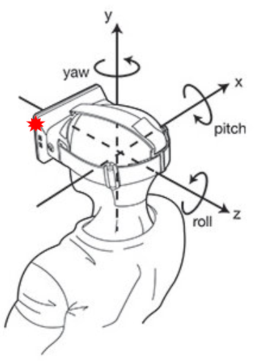
"Naive" Head-Mounted Measurements
The "Naive" Head-Mounted configuration places the sensors in a more realistic location. The sensor package is offset 4cm in each axis from the center of rotation (i.e. mounted on the user's head). With the accelerometer offset from the center of rotation, the sensor will experience acceleration due to gravity as well as acceleration due to rotation. In the naive configuration, the system makes no attempt to compensate for the acceleration due to rotation. The filter assumes the received accelerometer measurement is a noisy gravity vector and proceeds as before.
|
|
"Compensated" Head-Mounted Measurements
In the "Compensated" Head-Mounted configuration, the system attempts to compensate for the acceleration due to rotation. This requires knowledge of the headset angular velocity and angular acceleration, which we obtain from the gyroscope and a first order Euler approximation. Once the angular velocity and angular acceleration-dependent terms have been estimated, we subtract these values from the measured acceleration and pass the resulting gravity vector approximation to the filter.

|
|
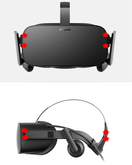
Constellation Head-Mounted Measurements
In the Constellation Head-Mounted configuration, the gyroscope has been removed from the system. Angular rate measurements are instead determined by a constellation of accelerometers. Cardou et al. and Zou et al. provide excellent descriptions of this technique.
The accelerometer constellation consists of eight accelerometers, arranged in symmetric pairs about the user's head. The key idea is that this symmetric pairing leads to cancelation when the measurements from paired accelerometers are summed. The angular acceleration terms drop out, and we can directly calculate the headset translational acceleration.
The resulting translational acceleration then feeds into additional calculations for the headset's angular and tangential accelerations. We then approximate the angular velocity using trapezoidal integration of the computed angular acceleration.
|
|
Side-by-Side Comparison
We simulated the headset rotating in all three axes. The simulation framework supports any input angular velocity signal; for these simulations, the angular velocity of all three axes was chosen to be a sine wave with a 144 deg/s amplitude and 2.5s period (parameters determined by the developers rotating their heads). The initial state estimate was initialized to a random quaternion of unit length.
The headtracker quickly converges to the true head orientation in all of our simulations, with each of the four system configurations. However, the compensated system does experience some jitter in the state estimate, likely due to our first order Euler approximation for the angular acceleration. The root mean square error (RMSE) and filter computation times provide useful metrics for comparing each configuration:
| ψ RMSE (deg) | θ RMSE (deg) | φ RMSE (deg) | Single Iter Comp (ms) | |
|---|---|---|---|---|
| Center of Head | 0.0354 | 0.0236 | 0.0173 | 0.2107 |
| Naive | 0.3097 | 3.3644 | 2.4064 | 0.2200 |
| Compensated | 0.3910 | 4.9697 | 2.9544 | 0.3311 |
| Constellation | 0.0752 | 1.0250 | 0.7659 | 0.8950 |
The four configurations we considered all show promising attributes for virtual reality headtracking. The performance of the accelerometer constellation is particularly exciting; while this configuration requires more than twice the computation time of other methods, the entire system is still fast enough to be integrated into a real VR rendering pipeline.
There are several directions for future work on this system. One opportunity is to fuse the angular rate measurements from a gyroscope with the accelerometer constellation. Another interesting study would be to implement a predictive scheme to compensate for the difference between the sensor measurement time and filter update time. Finally, we would like to deploy these systems on hardware!